UML Use Case Diagram
Jump to navigation
Jump to search
Use Case Basics⌘
- Use cases are used to model the requirements of a system (what a system is supposed to do)
- The key concepts associated with use cases are actors, use cases, and the subject.
Use Case Diagram⌘
- describes the relationships among a set of use cases and the actors participating in these use cases
- it does NOT describe behavior or flows (WHO and WHAT, not HOW)
Actor⌘
- a role played by an external entity - a user or any other system that interacts with the subject
- may represent roles played by human users, external hardware, or other subjects
- Notation: "stick man" icon (with the name above or below) or rectangle
Relationships Between Actors⌘
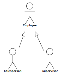
- Generalization
- Specialization
UseCase⌘
- the specification of a set of actions performed by a system and produce a result
- a complete set of actions that perform a function for a particular actor
- Notation: an ellipse (with the name inside or below) or rectangle with stereotype
Subject⌘
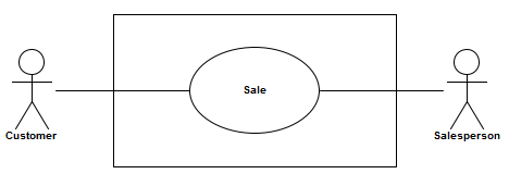
- a system (subject) is a box containing use cases
- defines boundaries and responsibilities
- actors are always external to a system
Relationships Between Actors and Use Cases⌘
- an association expresses a communication path between the actor and the use case
- directed association from the active to the passive element (who initiated the communication)
- association with multiplicity like 0..*, 2..*, *, etc
- at the actor end - more than one actor instance is involved in initiating the use case
- at the use case end - an actor can be involved in multiple use cases of that type
Relationships Between Use Cases⌘
Three types of relationship:
- «include»
- «extend»
- generalization
Include⌘
- defines that a use case contains the behavior defined in another use case
- behavior of the included use case is inserted into the behavior of the including use case
- included use case is not optional, and is always required
Include - common part⌘
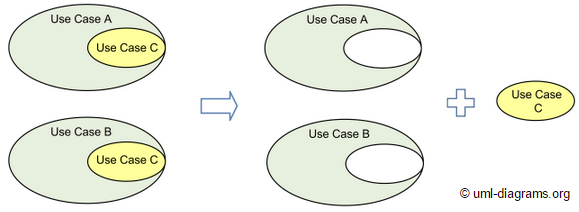
- include relationship is intended to be used when there are common parts of the behavior of two or more use cases
- this common part is then extracted to a separate use case, to be included by all the base use cases having this part in common
Include Example⌘
- basic flow of events is incomplete without the inclusion
Extend⌘
- a relationship from an extending use case to an extended use case
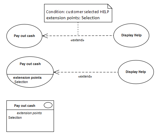
- specifies how and when the behavior defined in the extending use case can be inserted into the extended use case
- the extension takes place at extension point
- basic flow of events should still be complete
Extension Point⌘
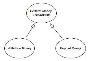
Generalization⌘
- the specific use case inherits the features of the more general use case
Abstract Use Case⌘
- does not provide a complete declaration and can typically not be instantiated
- is intended to be used by other use cases, e.g., as a target of generalization relationship
- the name of an abstract Use Case is shown in italics


