UML State Machine Diagram
Jump to navigation
Jump to search
State Machine Diagram⌘
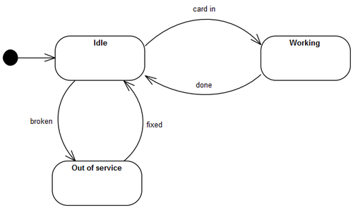
- State machine diagram is a behavior diagram which shows discrete behavior of a part of designed system through finite state transitions.
- State machine diagrams can also be used to express the valid interaction sequences (protocols) for parts of a system.
- Two kinds of state machines:
- behavior state machine,
- protocol state machine.
Behavior State Machine⌘
Vertex⌘
- Vertex is named element which is an abstraction of a node (State or Pseudostate) in a state machine graph.
- It can be the source or destination of any number of transitions.
State⌘
- State models a situation during which some invariant condition holds.
- In most cases this condition is not explicitly defined.
- Kinds of States:
- Simple State (has no internal vertices or transitions)
- Composite State (contains at least one region)
- Submachine State (refers to an entire State Machine)
Transition⌘
- Directed relationship between a source vertex and a target vertex.
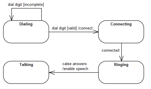
- Syntax: [<trigger> [‘,’ <trigger>]* [‘[‘ <guard>’]’] [‘/’ <behavior-expression>]]
- trigger specifies events that may cause state transition,
- guard is a boolean expression,
- optional behavior-expression is an expression specifying the effect (is executed when the transition fires)
Transition Kind⌘
The semantics of a Transition depend on its relationship to its source Vertex:
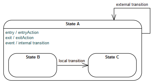
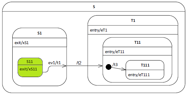
- external - transition exits its source vertex (executes exit action of source state)
- local - transition does not exit its containing State (exit action of the containing state will not be executed)
- Target vertex may be different from its source Vertex.
- Local transition can only exist within a composite State.
- internal is a special case of a local transition with the same source and target states,
- the state is never exited (and not re-entered)
- no exit or entry actions are executed
Internal Behaviors⌘
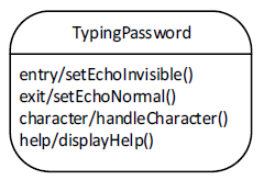
- entry - a Behavior which is performed upon entry to the State (entry Behavior).
- do - an ongoing Behavior (doActivity Behavior) that is performed as long as the modeled element is in the State or until the computation specified by the expression is completed.
- exit - a Behavior that is performed upon exit from the State (exit Behavior).
Completion Transitions, completion events⌘
- Completion transition has an implicit trigger (may have a guard).
- Completion event enables this trigger if all actions associated with the source state have completed execution:
- In simple states: a completion event is generated when the associated entry and doActivity actions have completed executing.
- In composite or submachine states: a completion event is generated when:
- all internal activities have completed execution, and
- if the state is a composite state, all its orthogonal regions have reached a final state, or
- if the State is a submachine State, the submachine State Machine execution has reached a final state.
Pseudo State⌘
- Pseudostate is an abstract vertex that describes different types of transient vertices in the state machine graph.
- Pseudostates are transitive - a compound transition execution simply passes through them, arriving on an incoming Transition and leaving on an outgoing Transition without pause.
Initial ⌘
- Initial Pseudostate represents a starting point for a Region.
- It is the source for at most one Transition, which may have an associated effect Behavior, but not an associated trigger or guard.
- There can be at most one initial Vertex in a Region.
Choice⌘
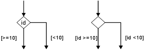
- Choice is used to realize a dynamic conditional branch.
- It allows splitting of compound transitions into multiple alternative paths.
- The decision on which path to take may depend on the results of Behavior executions performed in the same compound transition prior to reaching the choice point.
- If more than one guard evaluates to true, one of the corresponding Transitions is selected.
- If none of the guards evaluates to true, then the model is considered ill formed
Junction ⌘
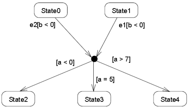
- Junction can be used to merge multiple incoming Transitions into a single outgoing Transition or,
- it can be used to split an incoming Transition into multiple outgoing Transition segments with different guard Constraints.
- Such guard Constraints are evaluated before any compound transition containing this Pseudostate is executed, which is why this is referred to as a static conditional branch.
Fork⌘
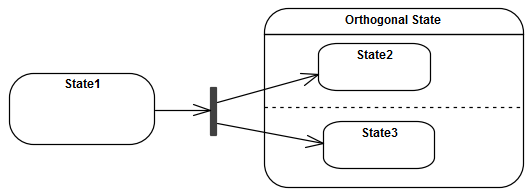
- Splits an incoming Transition into two or more Transitions terminating on Vertices in orthogonal Regions of a composite State.
- The Transitions outgoing from a Fork cannot have a guard or a trigger.
Join⌘
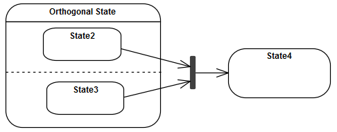
- Common target Vertex for two or more Transitions originating from Vertices in different orthogonal Regions.
- Transitions terminating on a Join cannot have a guard or a trigger.
Terminate ⌘
- Execution of the State Machine is terminated immediately.
- The State Machine does not exit any States nor does it perform any exit Behaviors. Any executing doActivity Behaviors are automatically aborted.
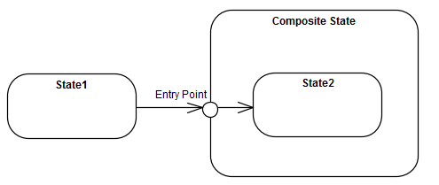
Entry Point ⌘
- Represents an entry point for a State Machine or a composite State that provides encapsulation of the insides of the State or StateMachine.
- In each Region of the StateMachine or composite State owning the Entry Point, there is at most a single Transition from the entry point to a Vertex within that Region.
If the owning State has an associated entry Behavior, this Behavior is executed before any behavior associated with the outgoing Transition. If multiple Regions are involved, the entry point acts as a fork Pseudostate.
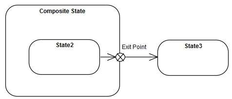
Exit Point ⌘
- Represents an exit point of a StateMachine or composite State that provides encapsulation of the insides of the State or State Machine.
- Transitions terminating on an exit point within any Region of the composite State or a State Machine referenced by a submachine State implies exiting of this composite State or submachine State (with execution of its associated exit Behavior).
If multiple Transitions from orthogonal Regions within the State terminate on this Pseudostate, then it acts like a join Psuedostate.
Shallow History⌘
- Represents the most recent active substate of its containing Region, but not the substates of that substate.
- Transition terminating on this Pseudostate implies restoring the Region to that substate.
- A single outgoing Transition from this Pseudostate may be defined terminating on a substate of the composite State.
- Shallow History can only be defined for composite States and, at most one such Pseudostate can be included in a Region of a composite State.
Deep History⌘
- Represents the most recent active state configuration of its owning Region.
- Transition terminating on this Pseudostate implies restoring the Region to that same state configuration.
- The entry Behaviors of all States in the restored state configuration are performed in the appropriate order starting with the outermost State.
- Deep History Pseudostate can only be defined for composite States and, at most one such Pseudostate can be contained in a Region of a composite State.
Final State⌘
- Final State is a special kind of State (not Pseudo State) signifying that the enclosing Region has completed.
- Transition to a Final State represents the completion of the behaviors of the Region containing the Final State.
Event Processing for State Machines⌘
The run-to-completion paradigm (in general)
- State Machine will perform its initialization during which it executes an initial transition, after which it enters a wait point.
- A wait point is represented by a stable state configuration. It remains thus until an Event stored in its event pool is dispatched.
- This Event is evaluated and a single State Machine step is executed.
- A step involves executing a transition and terminating on a stable state configuration (i.e., the next wait point).
- This cycle then repeats until the State Machine completes its Behavior.
- Event occurrences are detected, dispatched, and processed by the State Machine execution, one at a time.
Transition Execution Algorithm⌘
Protocol State Machine⌘
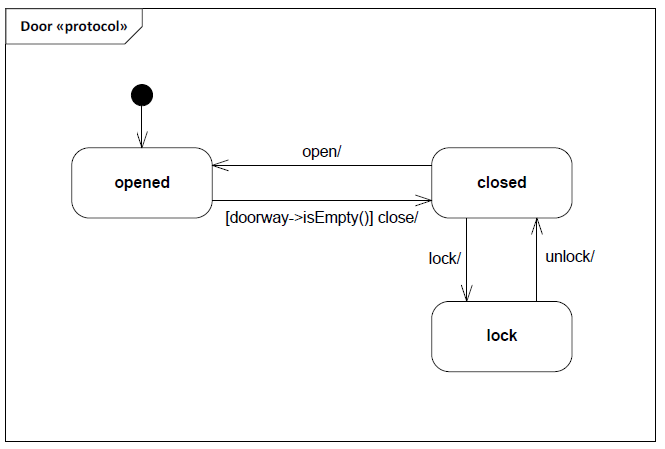
- Is always defined in the context of a classifier.
- Specify allowed invocation sequences (lifecycle of a classifier).
- Describes which operations of the classifier can be called in which state and under which condition.
Protocol State⌘
- A protocol State represents an exposed stable situation of its context Classifier.
- The States of a ProtocolStateMachine cannot have defined entry, exit, or doActivity actions.
Protocol Transition⌘
- A Protocol Transition specifies a legal Transition for an operation of the context Classifier.
- Syntax: [precondition] event / [postcondition]
