UML 2.5 Intro
Jump to navigation
Jump to search
Unified Modeling Language⌘
History of UML ⌘
UML was developed by Grady Booch, Ivar Jacobson and James Rumbaugh (The Three Amigos)
UML versions⌘
- 0.8 Booch & Rumbaugh 1995
- 0.9 The Three Amigos 1996
- 1.1 OMG 1997
- 1.2-1.5 OMG refinements 1998-2003
- 2.0 OMG major review and redesign 2003-2005
- 2.1.1, 2.1.2 OMG 2007
- 2.2 OMG 2009
- 2.3 OMG 2010
- 2.4.1 OMG 2011
- 2.5 OMG 2015 current version
UML specification: http://omg.org/spec/UML/Current
Overview ⌘
- OMG Standard
- The Unified Modeling Language (UML)
- Data modeling, business modeling (work flows), object modeling, and component modeling
- UML aims to be a standard modeling language which can model concurrent and distributed systems
- UML is a de-facto industry standard
- UML models may be automatically transformed to other representations (e.g. Java, PHP)
- UML is extensible, through profiles, stereotypes and tagged values
- A lot of other languages are based on UML (SysML, SoaML)
- Usually default language for a lot of architecture frameworks (MoDAF, DoDAF, NAF)
UML 2.5 Specification⌘
- This specification has been extensively re-written from its previous version to make it easier to read by removing redundancy and increasing clarity.
- The UML Infrastructure no longer forms part of the UML specification.
- Package Merge is not used within the specification.
- The compliance levels L0, L1, L2, and L3 have been eliminated, because they were not found to be useful in practice. A tool either complies with the whole of UML or it does not.
Parts of UML 2.5 Specification⌘
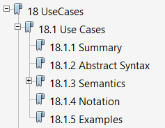
- Abstract Syntax contains one or more diagrams that define that capability in terms of the UML metamodel
- Semantics specifies the semantics (meaning) of all of the concepts.
- Notation specifies the notation corresponding to all of the concepts defined in the sub clause. Only concepts that can appear in diagrams will have a notation specified.
UML Features⌘
- Does not define method (see Unified Process)
- UML defines both:
- UML model (contains documentation and all relations)
- UML diagrams (partial graphic representation of a system's model)
- UML can model both views of the system:
- Static (structural)
- Dynamic (behavioral)
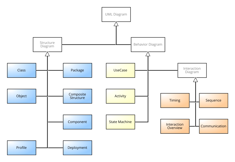
- Contains 14 different diagrams
UML Diagrams ⌘

Structure diagrams⌘
Structure diagrams represent the structure, they are used extensively in documenting the software architecture of software systems.
- Class diagram: describes the structure of a system by showing the system's classes, their attributes, and the relationships among the classes.
- Component diagram: describes how a software system is split up into components and shows the dependencies among these components.
- Composite structure diagram: describes the internal structure of a classifier and the collaborations that this structure makes possible.
- Deployment diagram: describes the hardware used in system implementations and the execution environments and artifacts deployed on the hardware.
- Object diagram: shows a complete or partial view of the structure of an example modeled system at a specific time.
- Package diagram: describes how a system is split up into logical groupings by showing the dependencies among these groupings.
- Profile diagram: operates at the metamodel level to show stereotypes as classes with the <<stereotype>> stereotype, and profiles as packages with the <<profile>> stereotype.
Behavior diagrams⌘
Behavior diagrams illustrate the behavior of a system, they are used extensively to describe the functionality of software systems.
- Activity diagram: describes the business and operational step-by-step workflows of components in a system.
- Use Case diagram: describes the functionality provided by a system in terms of actors, their goals represented as use cases, and any dependencies among those use cases.
- State machine diagram: describes the states and state transitions of the system.
Interaction diagrams⌘
Interaction diagrams, a subset of behavior diagrams, emphasize the flow of control and data among the things in the system being modeled:
- Sequence diagram: shows how objects communicate with each other in terms of a sequence of messages. Also indicates the lifespans of objects relative to those messages.
- Communication diagram: shows the interactions between objects or parts in terms of sequenced messages.
- Interaction overview diagram: provides an overview in which the nodes represent communication diagrams.
- Timing diagrams: a specific type of interaction diagram where the focus is on timing constraints.

