Data Modelling with UML
<slideshow style="nobleprog" headingmark="⌘" incmark="…" scaled="false" font="Trebuchet MS" >
- title
- Data Modelling with UML
- author
- Filip Stachecki (Filip@NobleProg.pl)
</slideshow>
Short Introduction to Data Modelling⌘
- Data modeling is used to define and analyze data requirements needed to support the business processes within the scope of corresponding information systems in organizations.
References⌘
- Keith Gordon, Principles of Data Management - Facilitating information sharing Second edition, BCS Learning & Development Limited
- David C. Hay, UML and Data Modeling: A Reconciliation, Technics Publications
- David C. Hay, Data Model Patterns: Conventions of Thought, Addison-Wesley Professional
Languages used to describe data⌘
- Many notations for data modeling:
ERD and other pre UML notations⌘
Entity–relationship diagram⌘
- Entity–relationship model (ER model) is a data model for describing the data or information aspects of a business domain or its process requirements
- Entity–relationship modeling was developed by Peter Chen and published in a 1976
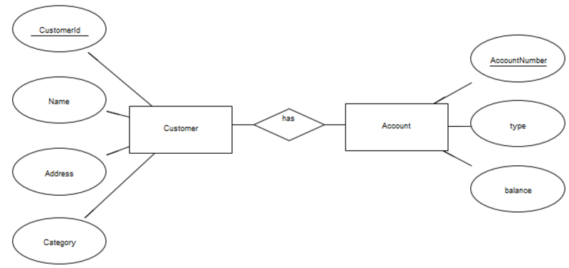
Entity–relationship meta model⌘
Entity types are represented by boxes, relationships by diamonds and attributes by ellipses attached to the entity type boxes.
Entity–relationship elements⌘
- Entity:
- something capable of an independent existence that can be uniquely identified
- thing of significance about which the organization wishes to hold information
- physical, tangible object: a house or a car, or a concept (intangible thing) such as a transaction, order or role.
- Entity type:
- category, definition of a set of entities
- an entity is an instance of a given entity-type
- Relationship:
- captures how entities are related to one another
- Attribute:
- describes an entity or a relationship, defines one piece of information
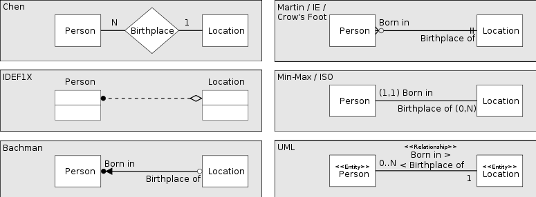
Entity–relationship cardinalities⌘
Different diagramming conventions⌘
Why data modelling is not database modelling⌘
- Data modeling is the process of creating a data model for an information system.
- Data modeling is used to define and analyze data requirements needed to support the business processes within the scope of corresponding information systems in organizations.
- Database model is a type of data model that determines the logical structure of a database and fundamentally determines in which manner data can be stored, organized, and manipulated.
Three levels of modeling⌘
Conceptual⌘
- the most abstract form of data model
- simplified, helpful for communicating ideas to a wide range of stakeholders
Logical⌘
- contains more details about structure of the data elements and the relationships
Physical⌘
- visually represents the structure of the data as implemented by a relational database schema
- must contain enough detail to produce a database
Concepts of storing the data ⌘
- Relational, Hierarchical, Object Oriented, etc...
Relational model⌘
- The most popular example of a database model
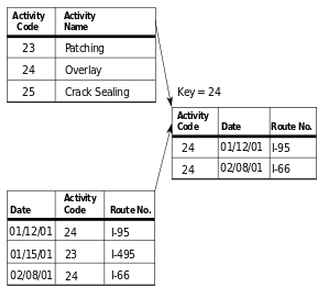
- All data is represented in terms of tuples (ordered list of elements), grouped into relations.
- Most relational databases use the SQL data definition and query language
Hierarchical model⌘
- A hierarchical database model is a data model in which the data is organized into a tree-like structure.
- The structure allows representing information using parent/child relationships:
- each parent can have many children, but each child has only one parent (1-to-many relationship)
- It was the first database model created by IBM in the 1960s
- Hierarchical database example used currently: XML file, Windows Registry
Hierarchical model example⌘
<?xml version="1.0"?>
<film_list>
	<film>
		<title>Pirates of the Caribbean</title>
		<director>Gore Verbinski</director>
		<cast>
			<actor sex="M">Johnny Depp</actor>
			<actor sex="M">Geoffrey Rush</actor>
			<actor sex="M">Orlando Bloom</actor>
			<actor sex="F">Keira Knightley</actor>
		</cast>
	</film>
	<film>
		<title>What Women Want</title>
		<director>Nancy Meyers</director>
		<cast>
			<actor sex="M">Mel Gibson</actor>
			<actor sex="F">Helen Hunt</actor>
			<actor sex="F">Marisa Tomei</actor>
		</cast>
	</film>
</film_list>
Object-oriented model⌘
- Information is represented in the form of objects as used in object-oriented programming.
- Object databases have been considered since the early 1980s.
- Most object databases also offer some kind of query language (e.g. Object Query Language)
NoSQL⌘
- A NoSQL or Not Only SQL database provides a mechanism for storage and retrieval of data that is modeled in means other than the tabular relations used in relational databases.
- NoSQL databases are finding significant and growing industry use in big data and real-time web applications.
- Example: MongoDB
UML and Data Modelling
Why do we need UML?⌘
Is UML for Data Modeling?⌘
- Object-oriented data requires to be stored after the program is completed (persistence).
- The way data is organized in object-oriented program is very different from the the way it's organized in relational database
- Example: OO inheritance is not directly supported in relational database
- OO world needs to be transformed to relational world
- Solution - use a subset of UML Class diagram's elements
Class Basics⌘
Element⌘
Metaclass Element
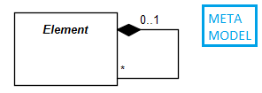
- An element is a constituent of a model.
- All elements are subclasses of Element
- Element can own other elements
- No notation for Element - it is abstract
Relationship ⌘
Relationship class
- Used to interconnect elements
- No notation for Relationship as it is abstract
Directed Relationship ⌘
DirectedRelationship class
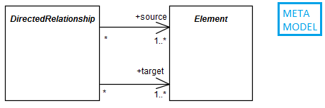
- a specialization of a relationship
- source elements want something - a client
- target element offers something - a supplier
Comment⌘
- a textual annotation that can be attached to an element
- may contain information that is useful to a modeler
- can be attached to more than one element
Classifier⌘
- an abstract base class
- describes a set of instances that have features in common
- Examples of Classifiers:
- Use Case
- Class
Feature⌘
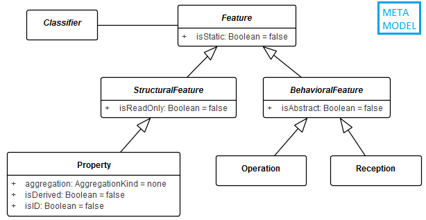
- declares a behavioral or structural characteristic of instances of classifiers
- structural feature describes a structure of an instance of a classifier (e.g. property)
- behavioral feature specifies an aspect of the behavior of classifier's instances (e.g. operation)
Property⌘
- a special structural feature that if it belongs to a class, is an attribute
- represents a declared state of one or more instances
Operation⌘
- a behavioral feature of a classifier, which specifies name, type, parameters, and constraints
- can have preconditions and postconditions
- can have a type (the type of the return parameter)
- example:
+ createWindow (location: Coordinates): Window
UML Class⌘
- describes a set of objects that share the same specifications of features (attributes and operations)
- is a special classifier
- an object is an instance of a class
- class name always in singular (Person, not People)
Entity Class⌘
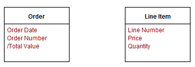
- Entity Class represents an entity
- Attribute is a characteristics of an entity class
- Attribute
- use: attribute name, isId, derived
- don't use: attribute visibility, read only
Mapping classes to tables⌘
- Simple approach: map class attribute to zero or more columns in a relational database
- Object-oriented Classes are mapped using one-to-one mapping only in very simple databases
- derived attributes are not mapped
- one attribute can map to several columns in the database
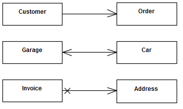
Association⌘
- specifies a relationship between instances
- describes a set of tuples whose values refer to typed instances
- declares that there can be links between instances of the associated types
Multiplicity⌘
- specifies how many objects of the opposite class an object can be associated with
- is a range of the minimum and maximum values
- syntax: number or min..max
| Multiplicity | Notation |
|---|---|
| zero | 0 or 0..0 |
| exactly one | 1 |
| zero or one | 0..1 |
| zero or more | 0..* or * |
| one or more | 1..* |
Multiplicity example⌘
Multiplicity - order and uniqueness⌘
- Multiplicity defines a specification of order and uniqueness of the collection elements.
- This option can specify whether the values should be unique and/or ordered.
- ordered: the collection of values is sequentially ordered (default: not ordered)
- unique: each value in the collection of values must be unique (default: is unique)
Property = End or Attribute⌘
- specifies whether one object can be accessed directly from another
Association as a relationship between entities⌘
- A relationship between two entities consists of two logical statements (one each way)
- Sytnax (by David Hay):
Each "Entity1" (may be|must be) "role name" (exactly one|one or more) "Entity2"
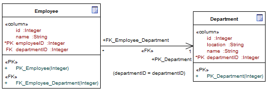
- Relationship:
- Each Employee must be employed in exactly one Department
- Each Department may be employer for one or more Employees
Association roles⌘
Association Mapping Exercise⌘
Many-to-many Association Mapping Exercise⌘
Many-to-many Association Mapping Exercise⌘
Association Class⌘
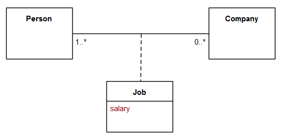
- An Association Class is both an Association and a Class.
- Describes a set of objects that each share the same specifications of features, constraints, and semantics.
Aggregation⌘
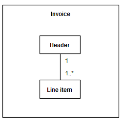
- shows how something (whole) is composed of parts
- parts can exist separately - can be shared
- precise semantics of aggregation varies by application area and modeler :)
Composition⌘
- a strict form of aggregation
- the whole is the owner of its parts
- parts can not be shared
- the existence of its parts depends on the whole
Aggregation / Composition Example⌘
Association / Composition Mapping⌘
- reading/writing/deleting objects from the database should map relationship type (association, aggregation, composition)
- relationships in relational databases can be implemented using foreign keys
N-ary association⌘
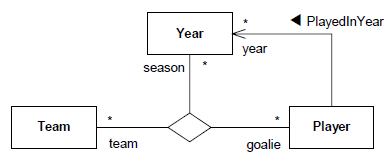
- if an association has more than two end points (here: ternary association)
- Notation: a rhombus is used as a connection point
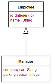
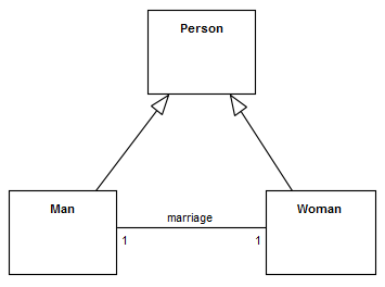
Generalization⌘
- relationship between a more general classifier and a more specific classifier
- each instance of the specific classifier is also an indirect instance of the general classifier
- the specific classifier inherits the features of the more general classifier
Generalization Example⌘
Sub-types in entity/relationship model⌘
Sub-types example⌘
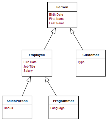
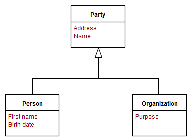
Inheritance example⌘
How can we map this structure in relational database?
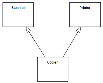
Multiple Inheritance⌘
Dependency ⌘
- a relationship that signifies that a model element(s) requires other model element(s) for their specification or implementation
- the complete semantics of the depending elements is dependent on the definition of the supplier element(s)
- the modification of the supplier may impact the client model elements
- the semantics of the client is not complete without the supplier
- the type of dependency can be specified by using a keyword or stereotype
Named Element⌘
- represents an element that may have a name and a visibility
| Visibility Kind | Notation |
|---|---|
| public | + |
| private | - |
| protected | # |
| package | ~ |
Namespace⌘
- named element that can own other named elements
- each named element may be owned by at most one namespace
- provides a container for named elements
- all the members of a namespace are distinguishable within it
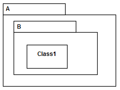
Package⌘
- used to group elements, and provides a namespace for the grouped elements
- qualified name:
package name::element name
Package Import, Access⌘
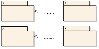
A package import is defined as a directed relationship that identifies a package whose members are to be imported by a namespace.
Two types:
- «import» for a public package import
- transitive: if A imports B and B imports C then A indirectly imports C
- «access» for a private package import
- intransitive
Package Import Example⌘
- elements in Types are imported to ShoppingCart, and then further imported to WebShop
- elements of Auxiliary are only accessed from ShoppingCart, and cannot be referenced from WebShop
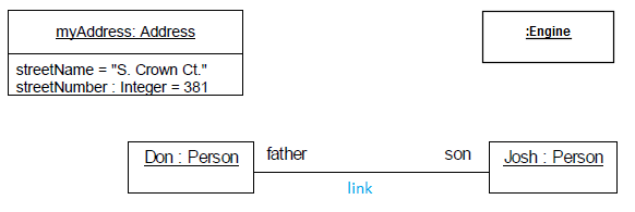
Instance ⌘
- is a concrete instance in the modeled system
- instance = object
Attributes
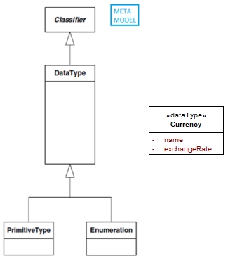
Data type⌘
A data type is a type whose instances are identified only by their value - two instances with the same value are indistinguishable.
A DataType may contain attributes to support the modeling of structured data types.
PrimitiveType⌘
A primitive type defines a predefined data type, without any relevant substructure.
Four instances of primitive type:
- Boolean (true, false)
- Integer (..., -1, 0, 1, ...) symbol for infinity - *
- UnlimitedNatural (0, 1, 2, ...)
- String
Enumeration⌘
An enumeration is a data type whose values are enumerated in the model as enumeration literals.
Enumeration in ER⌘
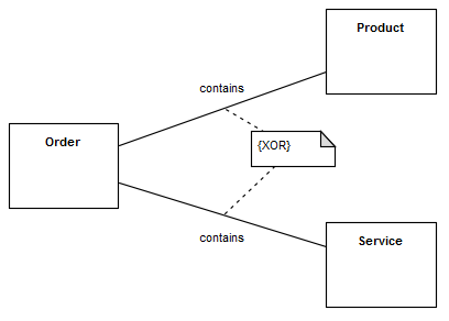
Constraint⌘
- condition or restriction related to an element
- it must always be true
- can be in formal (OCL) or human language
- syntax:
{ [name :] boolean expression }
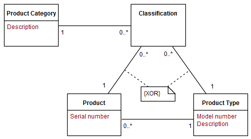
Constraints on relations⌘
Views of data models⌘
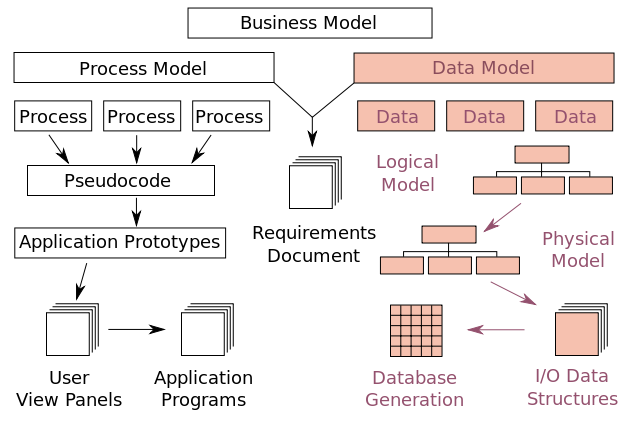
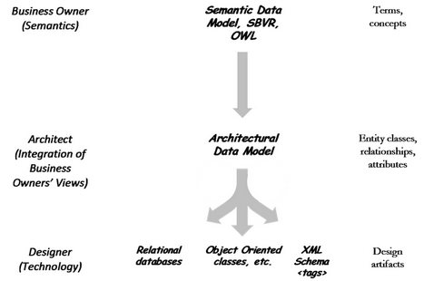
David C. Hay, UML and Data Modeling: A Reconciliation, Figure 1-1: The Players and Their Artifacts
Views:
- Views of the Business (planner, owner, architect)
- Views of Technology (designer, builder)
Each element has a different view of the world.
Other useful UML diagrams⌘
Composite structure diagram⌘
- Composite structure diagram can be used to specify internal structure of a class
Profile diagram⌘
- Profile diagram can be used as an extension mechanism to the UML.
- Custom "UML dialect" can be defined using stereotypes, tagged values, enumerations, and constraints.
Avoid Redundancies⌘
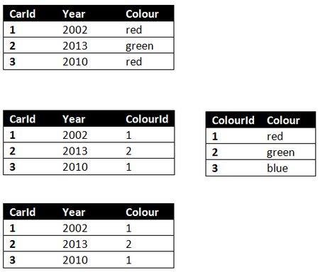
Data redundancy⌘
- Data redundancy occurs in database systems which have a field that is repeated in two or more tables.
- Data redundancy leads to data anomalies and corruption and generally should be avoided by design.
Database normalization⌘
- Normalization means decomposing a table into less redundant and smaller tables without losing information, defining foreign keys in the old table referencing the primary keys of the new ones
- The objective is to isolate data so that additions, deletions, and modifications of an attribute can be made in just one table and then propagated through the rest of the database using the defined foreign keys.
Stereotype⌘
- Formal extensions to existing model elements
- They do not introduce new elements
- They add semantics to existing model elements
- Elements can have multiple stereotypes
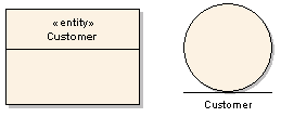
- Stereotype name goes above or before element name enclosed in «»
- special character not a pair of < or >
- Graphical symbols can be used to replace «»
- List of standard UML stereotypes: UML 2 Spec, Annex C: Standard Stereotypes
Design Patterns⌘
- Design pattern is a general reusable solution to a commonly occurring problem within a given context.
- It is a description or template for how to solve a problem that can be used in many different situations.
- Patterns are formalized best practices that the programmer can use to solve common problems when designing an application or system.
