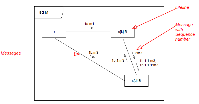
UML Communication Diagram
Jump to navigation
Jump to search
Communication Diagram⌘
- Describes interactions between objects.
- The sequencing of Messages is given through a sequence numbering scheme.
- Communication Diagrams correspond to simple Sequence Diagrams.
- Lifeline represents an individual participant in the interaction.
Message⌘
- A message is shown as a line from the sender to the receiver.
- The send and receive events may both be on the same lifeline.
- The form of the line or arrowhead reflects properties of the message:
Entity-Control-Boundary Pattern⌘
- Entity: objects representing system data
- Control: objects that manages the flow of interaction of the scenario (the logic of a system)
- Boundary: objects that interface with system actors
Entity-Control-Boundary Links⌘
|
Actor |
Boundary |
Control |
Entity |
|
|
Actor |
OK |
|||
|
Boundary |
OK |
OK |
||
|
Control |
OK |
OK |
OK |
|
|
Entity |
OK |
OK |


