Nato Architecture Framework (NAF) - 3.5 - NATO Systems View
NSV, NATO Systems View
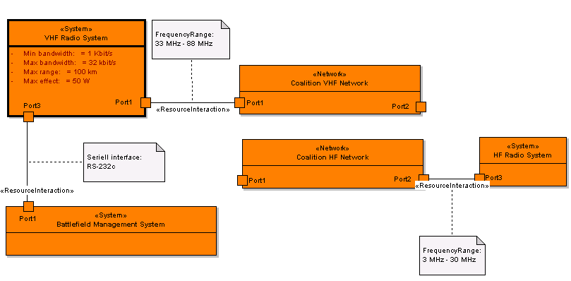
NSV-1, System Interface Description。
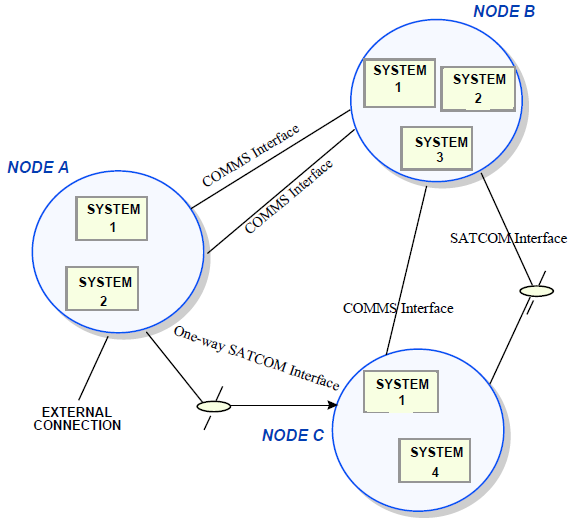
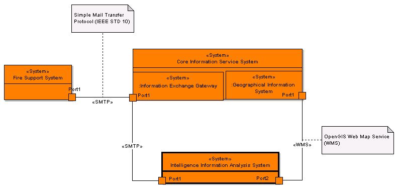
The purpose of the System Interface Description is to illustrate which systems collaborate in which way to support the operational domain‘s information and information exchange needs as defined in the Operational View; most notably in NOV-2 and NOV-3.
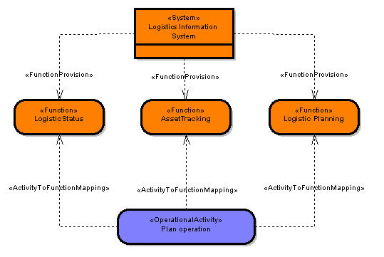
Example
NSV-1, System Interface Description。
Definition
- NSV-1 links together the NATO Operational View and the NATO System View by depicting which systems and system connections realize which information exchanges
A system is defined as:
any organised assembly of resources and procedures
united and regulated by interaction or interdependence
to accomplish a set of specific functions
- The term system in the NATO System View is used to denote software intensive systems, which may be classified as:
- Federation of Systems (FoS)
- System of Systems (SoS)
- subsystems
- system components
- Furthermore, the term system may denote logical systems as well as physical products, current systems as well as future systems
- The term 'system' is also used to denote a web service (or a composite web service, or a set of interacting and orchestrated web services, etcetera)
- Network components and other hardware components, such as routers, satellites and network segments are also seen as systems or elements of systems, and as such can be included in NSV-1 diagrams, especially if these diagrams are used to model distribution aspects
NSV-1, System Interface Description。
- A system‘s services are accessed through the system's interfaces
- An interface is a contract between providers and consumers of (system) services
- With regard to software intensive systems, the contract is a declaration of a coherent set of public system functionality
- The system's interfaces, in effect, specify the system‘s behaviour without specifying implementation specifics
- An NSV-1 connection between system interfaces is the systems representation of an NOV-2 needline or NOV-3 information exchange
- A single needline or information exchange may translate into multiple connections between system interfaces
- The following are documented in an NSV-1:
- systems and their interfaces
- system use dependencies between interfaces
- system collaborations (systems interacting with each other through their interfaces)
- distributions of software systems to hardware systems
- connections between hardware systems
- (optionally) patterns (essentially, patterns are standard system collaborations that have been proven to be sound solutions to known problems)
NSV-1, System Interface Description。
- NSV-1 is not intended for detailed descriptions
- Several aspects of a system‘s structural design are addressed in more detail in other system subviews
- A systems interface may be classified as a key Interface
- A key interface is defined as an interface where one or more of the following criteria are met:
- the interface spans organisational boundaries (may be across instances of the same system, but utilized by different organisations)
- the interface is mission critical
- the interface is difficult or complex to manage
- there are capability, interoperability, or efficiency issues associated with the interface
NSV-1, System Interface Description。
Development Guidance
- NSV-1 is best represented as a graphical diagram depicting how systems are collaborating through their interfaces to realize the information exchanges between operational nodes
- The diagram must be accompanied by a textual specification of all the graphical elements included in the diagram
- The specifications of systems and system interfaces should also include details concerning the functionality provided by each system; the procedures governing system implementation; the infrastructure supporting the systems; the quality with which the system offers its system services; and the means by which the system processes, manipulates, stores, and exchanges data
- Subsystem assemblies may be identified in NSV-1 to any level (i.e. depth) of decomposition that suits the architecture purpose
- On the other hand, NSV-1 may be limited to the identification of the key systems and key interfaces to improve understandability of the description
- Although the NSV-1 focuses on systems, this subview may also use concepts that broaden the concept of a system to include resources in general
- A system can be seen as just one type of resource
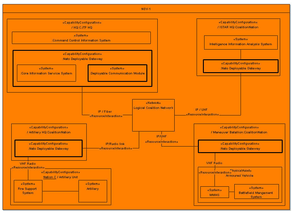
- The NSV-1 subview may include other resource types, such as physical assets (such as weapons systems, sensors and platforms) and capability configurations (combining the concept of a system with the concept of a role that is using that system)
NSV-1, System Interface Description。
- Consequently, NSV-1 may show:
- nodes
- capability configurations
- physical assets
- roles when addressing system distribution aspects, usage of systems, system deployments, or system support to information exchanges between nodes
- If showing all NSV-1 elements in one diagram makes the diagram unreadable, one should make use of a drill-down technique using multiple diagrams linked in a decomposition hierarchy
- If desired, annotations summarizing the system data exchanges carried by an interface may be added to NSV-1.
NSV-1, System Interface Description。
Running Example
NSV-1, System Interface Description。
Supporting NNEC Architecture Elements
- Location
- User
- Service (Application service)
- Component
- Component collaboration
Exercises。
- Create a diagram for a SATA hard drive in a USB pocket
Nato_Architecture_Framework_(NAF)_-_4.6_-_NATO_Meta_Model_-_NSV#NSV-1_System_interface_description
NSV-2, Systems Communication Description。
- The goal is to provide a comprehensive specification of:
- how systems are connected at a detailed infrastructural level
- what interfaces each system exposes (ports), the hardware interfaces used, and the protocols that govern transmission of data across the interface
- NSV-2 enables acquisition specialists and system engineers to quickly plan and visualize how communications between systems are to be implemented
- When NSV-2 is used as an analytical tool for existing systems, these subviews provide a detailed way to document the interfaces exposed by those systems
NSV-2, Systems Communication Description。
Definition
- Definition NSV-2 represents the specific communication systems pathways or networks and the details of their configurations through which the nodes and systems interface
- This subview focuses on the physical, infrastructural, communications aspects of the system interfaces as defined in NSV-1
- The graphical presentation and/or supporting text should describe all pertinent communications attributes, such as geographic location, bandwidth constraints, security, encryption, standards and protocols
- The NSV-2 subview is split into three subviews which define the communication links between systems:
- NSV-2a System Port Specification - defines the ports on each system, and the protocol / hardware stack that is specified or implemented for each of those ports
- NSV-2b System to System Port Connectivity - defines the connections between individual ports and shows the protocols and hardware specification used for each connection
- NSV-2c System Connectivity Clusters - defines the bundles of system to system connections that go to make up an inter-nodal connection (see NSV-1)
- NSV-2d Systems Communication Quality Requirements - NSV-2d specifies quality requirements applicable to communications between systems. This focus is available to offer separate attention to certain communication aspects, other than already specified in the other NSV-2 subviews.
NSV-2, Systems Communication Description。
Definition
- Key elements of the NSV-2 subview are:
- systems, ports and interfaces
- system-to-system connections
- nodes
- The elements are shown in different perspectives in the different subviews:
- In an NSV-1 subview the connections between nodes and between systems are shown
- In the NSV-2 subviews, more detail is added pertaining to the physical, infrastructural implementation of the communication links between systems. In particular, more detailed information is added pertaining to the ports on each system and the protocols applicable to communications
- The NSV-2a and NSV-2b subviews are also suited to include the NNEC-concept of a Service Interoperability Point (SIOP)
- A SIOP is a logical or physical reference point within an architecture where one or more key interfaces for international interoperability are physically or logically instantiated
- Within these two subviews a SIOP can be depicted as a higher-level system port
- The detailed technical specification of a SIOP is contained within a Service Interoperability Profile (SIP). SIPs are addressed in NTV-1 Technical Standards Profile.
NSV-2a, System Port Specification。
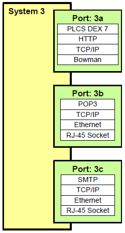
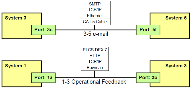
- Show the ports of a system and the protocols supported by each of those ports
- An NSV-2a product is intended to provide a specification for how a client in the environment of a system can connect to that system.
Example
NSV-2a, System Port Specification。
Definition
An NSV-2a product specifies the ports on a system, and the protocols used by those ports when communicating with other systems.
Development Guidance
- NSV-2a fully describe the communications protocols of each port on a system
- The subview comprises of one diagram for each system in the architecture
- Each port on the system is specified in terms of:
- its name,
- the communications protocols used (e.g. OSI Stack),
- the physical port specification (e.g. the physical element of the stack)
- In many cases, a physical port may support more than one protocol in parallel (e.g. a TCP/IP network supporting http, ftp, telnet, etc.)
- All supported protocols relevant to the architecture shall be shown
- The protocols will also be listed in NTV-1
- If a port supports a particular data protocol, supported by an information or data model, this will also be specified
- Any protocol referred to in an NSV-2a diagram must also be defined in the NTV-1 Technical Standards View
NSV-2a, System Port Specification。
Running Example
Exercise
- Create a diagram for a SATA hard drive in an USB pocket
NSV-2b, System to System Port Connectivity。
A System to System Port Connectivity subview is used to specify the physical, infrastructural nature of a connection between two systems. This may be an existing connection, or a specification of a connection that is to be made.
Example
NSV-2b, System to System Port Connectivity。
Definition
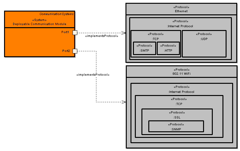
An NSV-2b product defines the protocol stack used by a connection between two ports. The ports may be on different systems. The NSV-2b subview is closely related to the NSV-2a subview which specifies the available protocols on each port. Any connection specified in an NSV-2b subview shall conform to the protocols specified on the corresponding port definitions in the NSV-2a subview.
NSV-2b, System to System Port Connectivity。
Development Guidance
- An NSV-2b product comprises a set of diagrams showing connections between ports of systems
- The architect may choose to create a diagram for each connection in the Architecture (recommended) or to show all the connections on one diagram (may be harder for readers to follow)
- Each diagram shall show:
- which ports are connected;
- the systems that the ports belong to
- the nature of the connection, in terms of the physical connectivity and any protocols that are used in the connection
- the quality requirements applicable to the connection.
- Any protocol referred to in an NSV-2b diagram must also be defined in the NTV-1 Technical Standards subview.
NSV-2b, System to System Port Connectivity。
Running Example
NSV-2c, System Connectivity Clusters。
- The purpose is to define the connectivity requirements between nodes, and is used for estimating requirements for physical routing and bandwidth
- Provides a different viewpoint on information already specified in the NOV-2, NOV-3, NSV-1, NSV-2a and NSV-2b subviews
- Useful when planning physical connections and routings between nodes
- Is also intended to aid analysis of the connectivity between systems within or between nodes
- In particular it is a useful way of highlighting redundancy issues, showing when too many or too few connections are used between nodes – i.e. there could be cost savings from using a common network, or there may be a need for redundancy to increase reliability.
NSV-2c, System Connectivity Clusters。
Example
Definition
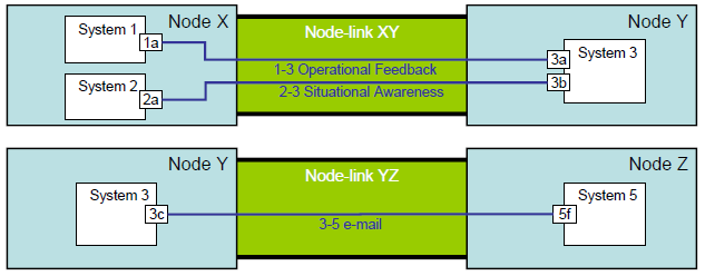
An NSV-2c product defines how individual connections between system ports are grouped into logical connections between nodes.
NSV-2c, System Connectivity Clusters。
Development Guidance
- NSV-2c products are usually derivable from elements and relationships established in other subviews, such as NOV-2, NSV-1, NSV-2a and NSV-2b, by summarizing the information contained therein
- The NSV-2c diagrams are derived by knowing which systems are deployed at given nodes and what connections exist between the ports of those systems
- An NSV-2c subview consists of a diagram for each logical inter-node connection.
- Each diagram shall show:
- the logical link between two nodes
- the system-to-system connections which run between those nodes
- which systems are located at each node
- which ports are used in the system-to-system connections
- what quality requirements are applicable
NSV-2d, Systems Communication Quality Requirements。
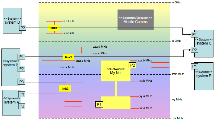
- The purpose of the Systems Communication Quality Requirements description (NSV-2d) is to specify specific quality requirements applicable to communications between systems
- NSV-2d focuses on specific categories of quality requirements for systems communication
- This focus is available to offer separate attention to certain communication aspects, other than already specified in the other NSV-2 subviews
- At the moment one category is supported:
- Electromagnetic Spectrum and Bandwidth;
- In addition to NSV-7, offering specification of quality requirements for systems in general, NSV-2d offers specification of quality requirements for specific system communication aspects.
NSV-2d, Systems Communication Quality Requirements。
Example
NSV-2d, Systems Communication Quality Requirements。
Definition
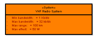
- The electromagnetic (EM) spectrum is becoming an increasingly congested area thus increasing the amount of EM interference (EMI)
- Greater restrictions on the use of the spectrum are making it more difficult for militaries to deploy new equipment utilizing bandwidths inside and outside the normal military operating frequency
- Therefore greater care must be taken at the design stages for any new piece of military equipment that operates in the EM spectrum
- Scientific analysis must be done to ensure the effects of EMI are clearly understood before final design and acquisition decisions can be made
- The electromagnetic spectrum and bandwidth description of subview NSV-2d is designed to assist with this analysis.
- The EM spectrum of interest for a given architectural model can be divided into different frequency bands, each with a regulated usage defined by international agreements managed by the ITU-R
NSV-2d, Systems Communication Quality Requirements。
Definition
- Frequency bands can be divided into two main categories:
- regulated frequency bands
- unlicensed frequency bands
- Systems that rely on the use of the EM spectrum will utilize different required bandwidths within the different frequency bands
- Depending on their use it is possible to consider the uplink channel bandwidth required as well as the downlink channel bandwidth required
- Uplink and downlink considerations will also be different depending on the direction type of the system
NSV-2d, Systems Communication Quality Requirements。
Development Guidance
- The following different direction types could be envisaged:
- terrestrial use
- aerial use (ground to UAV or aircraft, between aircraft etc)
- non-geostationary satellite use
- geostationary satellite use
- The reason for differentiating a set of different types is that interference issues may be very different depending on the direction type
- The type of use to which a system is put will also be important in order to manage issues such as interference
- The following system EM spectrum use types could be considered:
- communications
- radar
- receive-only detection
- target acquisition
- As an example it is well known that communications systems can suffer interference from weather radar systems and that the interference is dependent on different system characteristics
NSV-2d, Systems Communication Quality Requirements。
Development Guidance
- The above emphasis has been on systems that the blue force (friendly forces) would use
- It should be emphasized that of equal importance are the systems making use of the EM spectrum that a red force would use or neutrals would use or have in place, i.e. the planning needs to take existing on-site systems into account
- The systems in question will use a waveform that can be characterized by different parameters
- Examples of such parameters as they relate to communications systems are:
- data rate
- modulation
- coding
- figure of merit
- A more generic way of classifying the waveform can be derived by simply making use of the system designation such as
- GSM
- 3GPP WCDMA
- 3GPP2 CDMA2000
- WIMAX
- WLAN
- Etc.
NSV-2d, Systems Communication Quality Requirements。
Development Guidance
- The modulation scheme as well as coding will also be of great importance when determining the interference
- As an example, a communication system such as UMTS is essentially interference limited since the use of different codes is what separates different channels that overlap as far as frequency is concerned
- Thus the radio part of the system makes use of a closed loop control of the transmitted power of the individual phones in order to ensure that interference measured is kept within acceptable limits.
- In order to perform a more detailed systems planning there would seem to be a need to be able to consider the location of systems (blue (planned), red (assumed) or neutral (if known), knowledge whether they are fixed or mobile etc) that make use of the EM spectrum within the area of operation
- Knowledge about coverage areas associated with these locations as well as frequencies and bandwidths would also be important
- In order to consider interference issues in more detail, it may be of interest to allow for the association of different propagation models with the different systems under consideration
- Propagation models, at least for terrestrial use, usually take the type of terrain into account something that would make this possible only if the terrain type is known
NSV-2d, Systems Communication Quality Requirements。
Development Guidance
- Defining the terrain type may therefore also be a good idea. Examples of propagation models are:
- Delisle Egli
- Okumura Hata
- Apart from basic interference between different blue force systems discussions there are issues involving LPI (Low Probability of Interception) and LPD (Low Probability of Detection) that could need to be taken into account
- These terms are normally referred to as 'stealth'.
- Jamming possibilities is another issue that may need to be considered. A detailed consideration of these issues will require the definition of parameters associated with the type of communications as well as the equipment used such as antennas
- As an example, by reducing the bit-rate a WCDMA system can be made to become interference resistant as well as more resistant to jamming, provided the spreading codes used can be protected
- Making use of different types of antennas can ensure greater jamming resistance as well as decreasing interference towards friendly systems. Special antennas such as MIMO can also be used as a means of managing difficult terrain types such as urban ones
NSV-2d, Systems Communication Quality Requirements。
Running Example
NSV-3, Systems to Systems Matrix。
- The Systems to Systems Matrix provides detail on the interface characteristics described in the NSV-1 subview for the architecture, arranged in matrix form.
- An NSV-3 product allows a quick overview of all the interface characteristics presented in multiple NSV-1 diagrams
- The matrix supports a rapid assessment of potential commonalities and redundancies (or, the lack of redundancies)
Example
NSV-3, Systems to Systems Matrix。
Definition
- NSV-3 is a summary description of the system to system interfaces identified in NSV-1
- NSV-3 is similar to an NOV-3 information exchange matrix, with systems listed in the rows and columns of the matrix (instead of the node-node pairs per row), and with cells indicating a system interface pair (instead of information objects exchanged)
- Many types of interface characteristics can be presented in the cells of NSV-3
- The system interfaces can be represented using a number of different symbols and/or colour codes that depict different interface characteristics
- NAF does not specify the symbols to be used, but if it is used, the NSV-3 matrix must provide a key to the symbols
The following are examples:
- status (e.g., existing, planned, potential, deactivated)
- purpose
- classification level
- means
- standards
- key interfaces
NSV-3, Systems to Systems Matrix。
Development Guidance
- An NSV-3 product can be organised in a number of ways (e.g., by domain, by operational mission phase) to emphasize the association of groups of system pairs in context with the architecture purpose
- NSV-3 can be a useful tool for managing the evolution of systems and system infrastructures, the insertion of new technologies/functionality, and the redistribution of systems and processes in context with evolving operational requirements
Exercises。
- Use Sparx EA to design System to system matrix created in earlier exercises
Nato_Architecture_Framework_(NAF)_-_4.6_-_NATO_Meta_Model_-_NSV#NSV-3_System_to_system_matrix
NSV-4, System Functionality Description。
The primary purpose of the System Functionality Description is to:
- Describe systems that are outlined in NSV-1 in more detail, both in terms of structure (functional decomposition of systems) and behaviour (data flows between system components that realize certain system functions).
- Develop a clear description of the necessary system data flows between systems in accordance with NSV-11 data definitions
- Clearly describe the allocation of system functions to specific systems, system components and/or nodes and thus clearly delineate lines of responsibility
- Analyze the construction of NSV-1 systems to provide a basis for the determination of the quality requirements for systems (refer to NSV-7) and making decisions about streamlining, combining or omitting system functionality
- Provide a necessary foundation for depicting system constraints and the sequencing and timing aspect in NSV-10a, NSV-10b, and NSV-10c.
NSV-4, System Functionality Description。
Example
NSV-4, System Functionality Description。
Definition
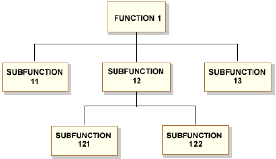
- To delineate a system‘s components, the NSV-4 product supports the development of system functional hierarchies and system functions
- The intention is to identify components by assigning the sole and exclusive responsibility for a certain system function to a system component
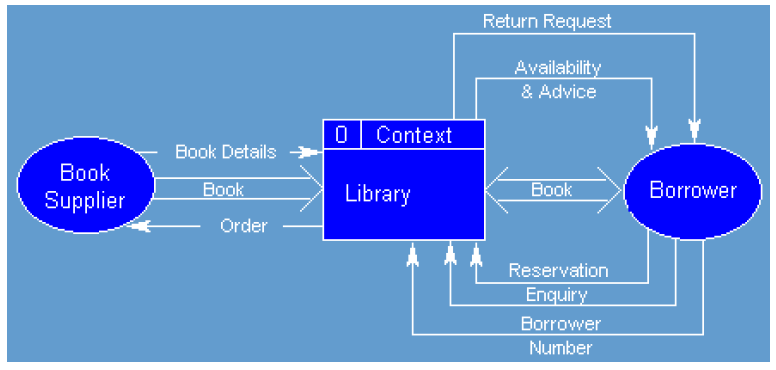
- NSV-4 also addresses collaboration between components through describing the system data flows between the system components that realize certain system functions
- In effect, this accomplishes a description of larger-grained systems in terms of structure (delineation of systems into functional components through hierarchical decomposition of system functions), and behaviour (data exchanges between the various functional components, and, in effect, also between systems)
- As a consequence, NSV-4 must be in accordance with other NSV subviews, such as NSV-1 (systems and interfaces), NSV-3 (system dependencies), NSV-6 (system data exchanges), and NSV-11 (data definitions)
NSV-4, System Functionality Description。
Definition
- Through functional decomposition of NSV-1 systems and addressing collaboration between the components in terms of data exchange, NSV-4, in fact, treats NSV-1 systems as white boxes and thus addresses the construction of an NSV-1 system.
- Other behavioural aspects, such as sequencing and timing issues are not addressed in NSV-4, but rather in NSV-10
- This division between NSV-4 and NSV-10 is analogues to that for operational activities in NOV-5 and NOV-6, respectively
- It must also be noted that quality of service requirements are also not addressed in NSV-4, but rather in NSV-7
- As a consequence, NSV-4 must be used in conjunction with NSV-7 to fully achieve NSV-4‘s purpose.
- System functions are not limited to internal system functions and can include Human Computer Interface (HCI) and Graphical User Interface (GUI) functions or functions that address the consumption or production of system data from/to external systems
- The external system data sources and/or sinks can be used to represent the human that interacts with the system or external systems
- The system data flows between the external system data source/sink (representing the human or system) and the internal system that realizes the HCI, GUI, or interface function can be used to represent human-system interactions, or system-system interfaces
- Standards that apply to system functions, such as HCI and GUI standards, are also specified in this product.
NSV-4, System Functionality Description。
Development Guidance
- Like NOV-5, NSV-4 may be hierarchical in nature and may have both a hierarchical decomposition model and a system data flow model
- The hierarchy model documents a functional decomposition
- The functions decomposed are system functions
- NSV-4 data exchanges must be in support of NOV-2 information needlines, NOV-3 information exchanges, and NSV-11 data definitions
- The scope of this product may be enterprise wide, without regard to which systems realize which functions, or it may be system specific
- Variations may focus on intra-nodal system data flow; inter-nodal system data flow; system data flow without node considerations; or function to system allocations (essentially relating NSV-4 functions to NSV-1 systems)
- Ensure that the functional connectivity is complete, i.e. that a system‘s required inputs and outputs are all satisfied
- Also ensure that the functional decomposition reaches an appropriate level of detail.
NSV-4, System Functionality Description。
Running Example
NSV-5, Systems Function to Operational Activity Traceability Matrix。
A Systems Function to Operational Activity Traceability Matrix depicts the mapping of operational activities to system functions and thus identifies the transformation of an operational need into a purposeful responsibility assigned to a system – i.e. how the system function supports the conducting of the operational activity.
Definition
- Operational activities do not necessarily map one-to-one to system functions
- Therefore, NSV-5 forms an integral part of the eventual complete mapping from operational capabilities to systems
- NSV-5 is an explicit link between the NATO Operational View and the NATO System View
- The operational activities are drawn from NOV-5. The system functions are drawn from NSV-4.
- The relationship between operational activities and system functions can also be expected to be many-to-many (i.e., one operational activity may relate to multiple system functions, and one system function may relate to multiple operational activities).
NSV-5, Systems Function to Operational Activity Traceability Matrix。
Development Guidance
An NSV-5 product seems best presented with the help of a matrix, with system functions as row headers, operational activities as column headers, and a code in the intersecting cells, explaining the nature of the mapping. E.g. the code could be a stoplight coloured circle to indicate the status of the system support. Red indicates functionality planned but not developed. Yellow indicates partial functionality provided or full functionality provided but system has not been fielded. Green indicates full functionality provided and system fielded. A blank cell indicates that there is no system support planned for an operational activity, or that a relationship does not exist between the operational activity and the system function. Please note that combinations of one or more of the mapping subviews NCV-5, NCV-6, NCV-7, NSOV-4, NSV-5 and NSV-12, can be used to construct (different variations of) a full mapping from capabilities to systems. The mappings form a line of reasoning through traceable linking of architecture elements from capabilities to systems.
NSV-5, Systems Function to Operational Activity Traceability Matrix。
Running Example
NSV-6, Systems Data Exchange Matrix。
- The Systems Data Exchange Matrix specifies the characteristics of the system data exchanged between systems
- This product focuses on automated information exchanges (from NOV-3)
- Non-automated information exchanges, such as verbal orders, are captured in the NATO Operational View only
- System data exchanges express the relationship across the three basic architecture entities of the NATO System View (systems, system functions, and system data flows) and focus on the specific aspects of the system data flow and the system data content
- These aspects of the system data exchange can be crucial to the operational mission and are critical to understanding the constraints introduced by the implementation.
NSV-6, Systems Data Exchange Matrix。
Definition
- NSV-6 presents information about system data exchange from NSV-subviews, such as NSV-1, NSV-3 and NSV-4, but with additional data attributes and properties
- NSV-6 also traces to the information exchanges detailed in NOV-3 that constitute the automated portion(s) of the NOV-3 information exchanges
- The operational characteristics of the NOV-3 information exchanges are enhanced with the corresponding system data attributes and properties
- For example, the performance attributes for the operational information exchanges are replaced by the actual system data exchange performance attributes for the automated portion(s) of the information exchange.
- It should be noted that a one-to-one relationship between NOV-3 information exchanges and NSV-6 data exchanges is not to be expected.
NSV-6, Systems Data Exchange Matrix。
Development Guidance
- NSV-6 is described in tabular format where a single row represents a system data exchange between a pair of systems (from NSV-1) or functional system components (from NSV-4)
- The table should be enhanced with data and data exchange specific attributes, such as periodicity, timeliness, throughput, size, information assurance, and security characteristics
- In addition, the system data elements, their format and media type, accuracy, units of measurement, and system data standard are also described in the table
- Ensure that an NSV-6 table is in accordance with NSV-1, NSV-4, and NSV-7 as well as NOV-2 and NOV-3. An NSV-6 table is usually sorted in a similar way as the corresponding NOV-3 table.
NSV-6, Systems Data Exchange Matrix。
Running Example
Nato_Architecture_Framework_(NAF)_-_4.6_-_NATO_Meta_Model_-_NSV#NSV-6_Systems_data_exchange_matrix
NSV-7, System Quality Requirements Description。
- One of the primary purposes of a System Quality Requirements Description (NSV-7) is to communicate which quality characteristics are considered most crucial for the successful achievement of the mission goals assigned to the system
- These particular parameters can often be the deciding factors in acquisition and deployment decisions, and will figure strongly in systems analyses and simulations done to support the acquisition decision processes and system design refinement.
NSV-7, System Quality Requirements Description。
Definition
- The NSV-7 product specifies the quality characteristics of systems, system hardware/ software items, their interfaces (system data carried by the interface as well as communications link details that implement the interface), and their functions
- It specifies the current quality requirements and the expected or required quality requirements at specified times in the future
- The quality requirement categories are selected by the architect and end user community.
- The complete set of quality requirements may not be known at the early stages of architecture definition, so it is to be expected that this product will be updated throughout the system‘s specification, design, development, testing, and possibly even its deployment and operations life-cycle phases.
NSV-7, System Quality Requirements Description。
Definition
- NSV-7 builds on other NSV-subviews, such as NSV-1, NSV-2, NSV-4, NSV-6 and NSV-11 by specifying quality requirements for:
- systems and interfaces (defined in NSV-1)
- system ports and communications (defined in NSV-2)
- system functions (described in NSV-4)
- system data exchange attributes (defined in NSV-6)
- data definitions (defined in NSV-11)
- If the future quality expectations are based on expected technology improvements, then the quality requirements and their time periods will be coordinated by using a Systems Technology Forecast (NSV-9)
- If quality improvements are associated with an overall system evolution or migration plan, then the time periods in NSV-7 will be coordinated with the milestones in a Systems Evolution Description (NSV-8).
NSV-7, System Quality Requirements Description。
Development Guidance
- An NSV-7 product is best represented in tabular form, where row headers are formed by the essential elements of the various subviews that relate to NSV-7 (NSV-1 for systems, NSV-2 for system connections, etc...)
- The column headers are formed by the various types of quality requirements
- The cells may contain values, ranges of values, concrete values, estimated values, or soft values, depending on the nature of the quality requirements category. Note that the term system may represent a system of systems or a Federation of Systems as in the case of the NII
- Often, systems have to collaborate in order to provide a service to the users
- In such a case, the quality requirements at service level are an emergent quality of all systems working together (i.e. of a system of systems)
- The level of service quality for the system of systems may be quite different from the levels of system quality of the separate systems involved
- In the worst case, the level of service quality is a function of the system or collaboration mechanism that forms the 'weakest link'
- The quality requirements for a system of systems, or a Federation of Systems providing a service must be in accordance with service definitions, including service quality requirements definitions, as defined in NSOV-2
- Please refer to NSV-12 for an NSV-1 system to NSOV-2 service mapping
- A similar 'system of systems' reasoning is adequate at one level of detail down, where system components collaborate to realize a system
- Pay specific attention to the balancing of quality requirements
NSV-7, System Quality Requirements Description。
Development Guidance
Design Scenarios
- Often, one category of quality requirements influences other categories of quality requirements in a negative way. E.g. one may expect it to be very difficult or at least very costly, to design a system that is both highly performent (e.g. real-time, high-volume data exchange, with very short response times) and highly secure (requiring a lot of overhead and delay to authenticate, encrypt/ decrypt, monitor and verify, etcetera)
- In such cases, the architect should provide multiple design scenarios, offering design solutions with varying emphasis on certain categories. E.g. three scenarios: one with emphasis on high performance, one on optimal security, and one somewhere in the middle (where security is relaxed in favour of higher performance where needed, and where high performance is sacrificed to ensure a high security level where it is most critical)
- Which scenario is ultimately chosen is the decision and responsibility of the stakeholders
- Some example categories are: latency, timeliness, throughput, availability, reliability, confidentiality, integrity, frequency, periodicity, format, and volume.
NSV-7, System Quality Requirements Description。
Running Example
NSV-8, Systems Evolution Description。
A Systems Evolution Description, when linked together with other evolution products such as NCV-3a, NPV-1, NSV-9 and NTV-2, provides a clear definition of how the architecture and its systems are expected to evolve over time.
In this manner, the product can be used as an architecture evolution project plan or transition plan.
Definition
An NSV-8 product describes plans for modernizing systems over time.
Such efforts typically involve the characteristics of:
- evolution (changing a system‘s quality, functionality or implementation, both technical and managerial, in order to ensure that the system meets current and future operational requirements in a cost effective way); or
- migration (the process of transferring (part of) a system to operate in a different environment, e.g. with a different operating system, platform, database, infrastructure, etcetera)
The two thrusts are often combined.
This product builds on other products and analyses, in that planned capabilities and requirements that relate to performance parameters (of NSV-7 and NSOV-2) and technology forecasts (of NSV-9) are accommodated in this product.
If the architecture describes a communications infrastructure, then a planned evolution or migration of communications systems, communication links, and their associated standards can also be described in this product.
Nato_Architecture_Framework_(NAF)_-_4.6_-_NATO_Meta_Model_-_NSV#NSV-8_System_evolution_description
NSV-9, Technology Forecast。
The purpose of the Technology Forecast is to identify relevant emerging technologies, and to ensure that the architecture benefits from it, or is easily adapted to it
NSV-9 provides a summary of emerging technologies that impact the architecture and its existing planned systems
The focus will be on the supporting technologies that may most affect the capabilities of the architecture or its systems
NSV-9, Technology Forecast。
Definition
- The NSV-9 subview defines the underlying current and expected supporting technologies
- It is not expected to include predictions of technologies
- Expected supporting technologies are those that can be reasonably forecast given the current state of technology and expected improvements
- New technologies will be tied to specific time periods, which can correlate against the time periods used in NSV-8 milestones
- NSV-9 provides a detailed description of emerging technologies and specific hardware and software products
- It contains predictions about the availability of emerging technological capabilities and about industry trends in specific time periods
- The specific time periods selected (e.g., 6-month, 12-month, 18- month intervals) and the technologies being tracked will be coordinated with architecture transition plans (see NSV-8)
- That is, insertion of new technological capabilities and upgrading of existing systems may depend on or be driven by the availability of new technology
NSV-9, Technology Forecast。
Definition
- The forecast includes potential technology impacts on current architectures and thus influences the development of transition and objective (i.e., target) architectures
- The forecast will be focused on technology areas that are related to the purpose for which a given architecture is being described and will identify issues affecting that architecture.
- If standards are an integral part of the technologies, important to the evolution of a given architecture, then it may be convenient to relate NSV-9 to NTV-1 and/or NTV-2. NSV-9 forecasts relate to the Technical Standards Profile (NTV-1) in that a timed technology forecast may contribute to the decision to retire or phase out the use of a certain standard in connection with a system element
- Similarly, NSV-9 forecasts relate to NTV-2 Technical Standards Forecast in that a certain standard may be adopted depending on a certain technology becoming available
NSV-9, Technology Forecast。
Development Guidance
- NSV-9 is constructed as part of a given architecture and in accordance with the architecture purpose
- Typically, this will involve starting with one or more overarching reference models or standards profiles to which the architecture is subject to using
- Using these reference models or standards profiles, the architect will select the service areas and services relevant to the architecture (as in NSOV-1)
- Per service area (or per service) the architect can then list forecasted technology for each of the specific time periods
- This is best presented using a table, where each forecasted technology occupies a row, grouped according to services or service areas, and with time periods as column headers
- Alternatively, this table may be enhanced with additional columns for impacted NSV-elements, such as NSV-1 systems or interfaces, NSV-2 system connections, NSV-4 system functions, or NSV-11 data entities
Nato_Architecture_Framework_(NAF)_-_4.6_-_NATO_Meta_Model_-_NSV#NSV-9_Technology_forecast
NSV-10, Systems Rules, Sequence & Timing Description。
- Many of the critical characteristics of an architecture are only discovered when an architecture‘s dynamic behaviours are defined and described
- These dynamic behaviours concern the timing and sequencing of events that capture system quality characteristics of an executing system
- Behaviour modelling and documentation is key to a successful architecture description, because it is how a future system behaves that is crucial in many situations
- Although knowledge of the functions and interfaces is also crucial, knowing whether, for example, a response should be expected after sending message X to node Y can be crucial to successful overall operations.
- Three types of models may be used to adequately describe the dynamic behaviour and performance characteristics of a System View:
- Systems Rules Model (NSV-10a)
- Systems State Transition Description (NSV-10b)
- Systems Event-Trace Description (NSV-10c)
- NSV-10b and NSV-10c may be used separately or together, as necessary, to describe critical timing and sequencing behaviour in the NATO System View
- Both types of diagrams are used by a wide variety of different system development methodologies.
- Both NSV-10b and NSV-10c describe system responses to sequences of events
- Events may also be referred to as inputs, transactions, or triggers
- When an event occurs, the action to be taken may be subject to a rule or set of rules as described in NSV-10a.
NSV-10a, Systems Rule Model。
The purpose of the Systems Rule Model is to allow understanding of behavioural rules and constraints imposed on systems and system functions.
Definition
- Systems rules are constraints on an architecture
- While other NSV products (e.g., NSV-1, NSV-2 and NSV-11) describe the static structure of systems, they do not describe, for the most part, how these systems interact.
- At the systems level, NSV-10a describes the rules under which the architecture or its systems behave under specified conditions
- Rules are statements that define or constrain some aspect of the operational domain
- Whereas the Operational Rules Model (NOV-6a) focuses on constraints on operational requirements, NSV-10a focuses on constraints on system requirements, inferred from operational requirements
- As the operational rules in NOV-6a can be associated with the NOV-2, NOV-3 and NOV-5 nodes, information exchanges and operational activities, the system rules in NSV-10a can be associated with e.g. NSV-1, NSV-2 and NSV-4 systems, interfaces, connections, and system functions.
NSV-10a, Systems Rule Model。
Development Guidance
- Systems rules may be expressed in natural language, as with NOV-6a:
- Imperative
- Conditional Imperative
- However, with potentially complex system rules it may be more useful to express these rules using Object Constraint Language (OCL)5 or Object-Role Models (ORM).
Running Example
NSV-10b, Systems State Transition Description。
- The explicit time sequencing of system interaction in response to external and internal events is not fully expressed in NSV-1, NSV-2 and NSV-4
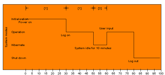
- A Systems State Transition Description (NSV-10b) can be used to describe the explicit sequencing of system interactions, using states and state transitions, brought on by triggers and events.
- A state transition description can often allow quick analysis of the completeness of the rule set, and detection of dead ends or missing conditions
- These errors, if not detected early during the systems analysis phase, can often lead to serious behavioural errors in fielded systems, or to expensive correction efforts.
NSV-10b, Systems State Transition Description。
Definition
- The product relates states, events, and actions
- A state and its associated action(s) specify the response of a system to events
- When an event occurs, the next state may vary depending on the current state (and its associated action), the event, and the rule set
- A change of state is called a transition
- Each transition specifies the response based on a specific event and the current state
- Actions may be associated with a given state or with the transition between states.
Development Guidance
- Best developed using a state machine
NSV-10c, Systems Event-Trace Description。
Systems Event Trace Descriptions are valuable for moving to the next level of detail from the initial systems design, to help define a sequence of system interactions, and to ensure that each participating system or human role has the necessary information it needs, at the right time, in order to perform its assigned functionality.
Definition
- The NSV-10c subview provides a time-ordered examination of system data exchanges between participating systems (external and internal) or human roles, as a result of a particular scenario or situation
- Each particular scenario or situation may reflect system-specific aspects or refinements of critical sequences of events described in the NATO Operational View (e.g. such as described in NOV-5 and/or NOV-6)
- NSV-10c can be used by itself or in conjunction with other system subviews (e.g. NSV-4, NSV-6, or NSV-10b) to describe dynamic behaviour of systems.
NSV-10c, Systems Event-Trace Description。
Development Guidance
- UML sequence diagrams may be used to model NSV-10c
- Each diagram should depict a different scenario
Running Example
NSV-11, System Data Model。
The purpose of a data model is to enable analysis, design and implementation of the data presentation, handling and storage functionality of an information system
Definition
- A data model should not be confused with an information model
- Although the distinction between the two is not clear, they at least serve different purposes
- There is a grey area where information models and data models overlap
- A data model is the representation of an information model in a form that is specific to a particular paradigm or theory on the representation, storage and handling of data, often reflecting a certain type of data store or repository technology
- Data models are often distinguished as logical (NSV-11a) or physical (NSV-11b) data models
- The term conceptual data model is also widely used, but seems to often equate to a higher-level logical data model in that it shows only the key data elements
- The purpose of a conceptual data model seems to be the communication of the main design decisions at the logical data level, to decision makers
- The terms 'conceptual data model', 'information model' and conceptual information model' are often used interchangeably, and the distinction is not clear
- Data elements, whether they are defined at the logical or physical level must be used consistently within other system subviews, such as NSV-1 (specifying interfaces), NSV-4 (describing data flows), and NSV-6 (describing data exchanges between systems)
- There is a close relationship between the integrated dictionary of NAV-2, the information model of NOV-11b.
NSV-11a, Logical Data Model。
The purpose of distinguishing logical from physical data models can be found in the fact that logical models allow analysis of a system‘s data definition aspect, without consideration of implementation specific or product specific issues. Another purpose is to provide a common dictionary of data definitions to consistently express subviews wherever logical-level data elements are included in the descriptions.
Definition
The logical data model is a generalized formal structure in computer science. As such it directly reflects the paradigm or theory oriented mapping from the information model to the data model. The most predominant of such mappings are the ones reflecting relational calculus (entity-relationship-attribute) and object-orientation (class-object-method-property).
NSV-11a, Logical Data Model。
Development Guidance
- The appropriate way to develop a logical data model depends on the technology chosen as the main design solution (e.g. relational calculus or object-orientation)
- For relational calculus, a logical data model seems best described using:
- an entity-relationship diagramming technique, such as provided by Chen, Bachman and Martin
- by OMG‘s UML class and object diagrams, that offer all the elements needed to develop both entity-relationship-diagrams (class diagrams) and Object-Oriented models (class and object diagrams)
NSV-11b, Physical Data Model。
Physical data models allow analysis of a system‘s data implementation aspect, with consideration for a specific product. Other purposes can be found in:
- Providing as much detail as possible on data elements exchanged between systems, thus reducing the risk of interoperability problems.
- Providing data structures for use in the system design process, if necessary.
- Providing a common dictionary of data implementation elements (e.g. tables and records in a relational database schema) to consistently express subviews wherever physical-level data elements are included in the descriptions.
Definition
- Definition The physical data model specifies how the logical data model will be instantiated in a particular product
- The most predominant of such products are the RDBM (database schema)
- Object repository products also exist, but are less often encountered
- In addition, this subview may employ other technology mechanisms, such as flat files
- The essential elements of a physical data model (in the case of a relational database) are: tables, records and keys
- In a true object-oriented data model, all data elements are expressed as objects; whether they are classes, instances, attributes, relationships, or events.
NSV-11b, Physical Data Model。
Development Guidance
- Depends on the product chosen
- For RDBMS entity-relationship diagramming technique is used
- An example of such a technique is provided by Chen, Bachman and Martin, or by OMG‘s UML class and object diagrams
- The techniques offer all the elements needed to develop both entity-relationship-diagrams (UML class diagrams) and Object-Oriented models (UML class and object diagrams).
Nato_Architecture_Framework_(NAF)_-_4.6_-_NATO_Meta_Model_-_NSV#NSV-11_Systems_data_model
NSV-12, Service Provision。
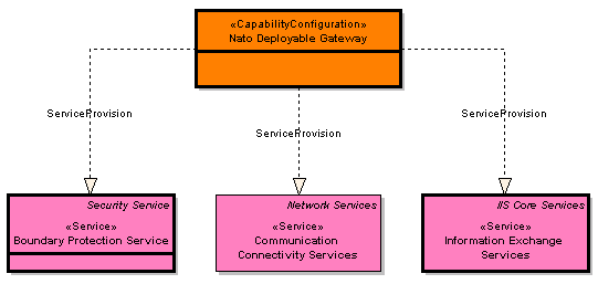
The purpose of the Service Provision subview (NSV-12) is to illustrate which systems contribute to the provision of which services.
Example
NSV-12, Service Provision。
Definition
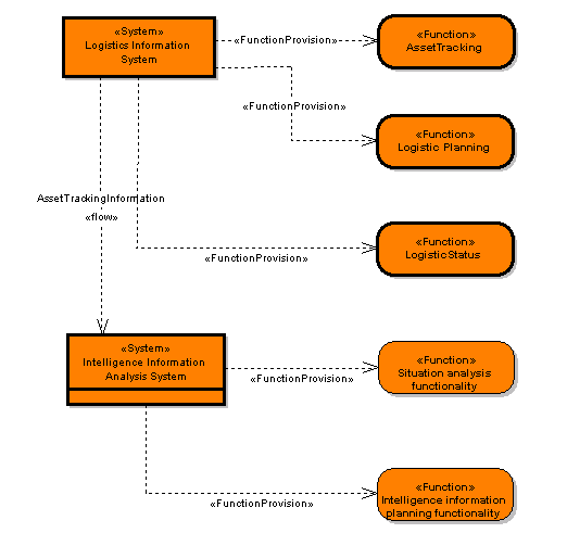
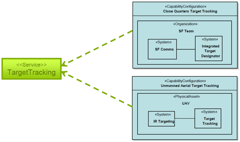
- The NSV-12 subview is a mapping of systems, as identified in NSV-1, to services, as defined in NSOV-2.
- If more detail is required (i.e. beyond the system level), system functions, as defined in NSV-4, can be mapped to services as well
- This mapping can be either direct or through an intermediary mapping from NSV-4 system functions to NSV-1 systems.
- If the concept of a system is used to mean the more general concept of a type of resource, it is allowed to include concepts reflecting other types of resources, such as capability configurations, physical assets and roles.
NSV-12, Service Provision。
Development Guidance
- This subview is best expressed using a matrix or a diagram as presented in the example below
- In a matrix, row headers should be NSV-1 systems (or resources)
- The NSOV-2 services should be entered as column headers
- Cells at the intersections may contain simple checkmarks or a more elaborate code that convenes information on the relationship between systems and services
- Please note that combinations of one or more of the mapping subviews NCV-5, NCV-6, NCV-7, NSOV-4, NSV-5 and NSV-12, can be used to construct (different variations of) a full mapping from capabilities to systems
- The mappings form a line of reasoning through traceable linking of architecture elements from capabilities to systems.
NSV-12, Service Provision。
Running Example
Nato_Architecture_Framework_(NAF)_-_4.6_-_NATO_Meta_Model_-_NSV#NSV-12_Service_provision
