UML Deployment Diagram
Deployment Diagram⌘
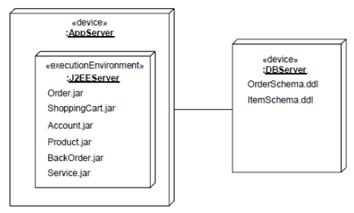
- Describes the hardware used in system implementations, execution environments and artifacts deployed on the hardware.
Node⌘
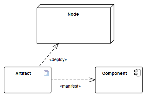
- A Node is computational resource upon which Artifacts may be deployed.
- Nodes may have complex internal structure (can only consist of other nodes)
- Two types of nodes:
- Device (physical machine components) - e.g. application server, client workstation, mobile device
- Execution Environment (software systems) - e.g. OS, workflow engine, database system, J2EE container
Artifact⌘
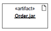
- An artifact represents some item of information that is used or produced by a software development process or by operation of a system.
- An artifact represents concrete elements in the physical world.
- Examples of artifacts: model files, source files, scripts, executable files, database tables, word-processing documents, and mail messages.
Communication Path⌘
- A communication path is an association between two nodes, through which they are able to exchange signals and messages.
- It usually represents physical connection between devices or some protocol between execution environments.
Deployment⌘
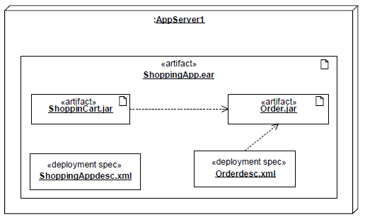
- A deployment is a dependency relationship which describes allocation (deployment) of an artifact to a deployment target.
Deployment Specification⌘
- A deployment specification specifies a set of properties that determine execution parameters of a component artifact that is deployed on a node.


